Spectra of electrons
reflected from the
Theory
Fig. 1. Model of scattering Analytical description of electron interaction with solids is
based on kinematics and dynamics of elementary act of collision between two
particles. One can use classical approach as long as it is possible to neglect
quantum phenomena. This is a case when wavelength of a particle is below atomic
distance in solids (~ 0.1 nm). Wavelength of electrons reaches this limit at
their energies of below 150 eV. where g –
scattering angle, D – energy loss. Calculation of differential elastic cross section of electron
scattering is a complex quantum mechanical problem.
According to Mott [5] for no
polarized relativistic beam differential by angle cross section of electron
scattering on atom can be expressed in terms of two complex amplitudes. For the
scattering event takes place in unshielded field of atoms kernel (Coulomb potential) Mott has provided analytical expression for those functions.
As long as electron energy rises, the effect of shielding gets developed at
higher scattering angles. This requires complex calculations to be carried out
to find differential cross section of electron scattering [5]. Riley, MacCalum
and Biggs [6] have evaluated differential cross sections of
elastic electron scattering for all atomic numbers (up to 94) for energy
ranging between 1 keV to 256 keV. They have proposed approximation for elastic
scattering indicatrix valid for energy from hundred eV: where Am, B, Cn –
parameters depend on energy of incident electrons and atomic number of
scattering media Z, Pn(x) –
Legendre polynomials. Fig. 2 demonstrates differential cross sections of elastic
scattering of electrons on different target materials and incident electron
energy.
Fig. 2. Elastic cross section
Expression for elastic scattering of electrons on solid matter does not change
much compared to elastic scattering on separate atom. In contrast, expression
for inelastic interaction (second term of (1)) experiences a drastic change due
to collective effects during electron passing through solid media.
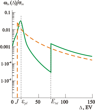
where J – fitting parameter that effectively averages thresholds of real
inelastic processes, Cin – coefficient that depends on target
material. Exponent equal to 2 because there are ionization losses that contribute
most to slowing down of electrons with energy above few keV, and the value has
the same order of magnitude like volume plasmon, cross section of excitation of
which is maximal among other inelastic processes.
Akerman and Khlupin have provided the tables of calculated electron free path
values for elementary processes, as well as average electron energy losses per
path unit for incident electron energy in the range of 0.1…100 keV [9]. Those
calculations are in a good agreement (10…15%) with experimental data for the
wide range of atomic numbers.
Fig. 3. Inelastic cross section
Multiple scattering of
electrons The modern methods of theoretical description of multiple
scattering of electron beams can be divided into analytical methods of solving
corresponding transport equations and numerical methods. Analytical methods
allow to process experimental data in terms of clear physical parameters, solve
ill-conditioned and inverse problems of scattering theory.
However, to
achieve highly accurate description of electron scattering on heterogeneous
target one should consider both elastic and inelastic scattering based exact
solution of boundary problem.
where n0 – concentration of target atoms,
s – complete scattering cross section,
h=cosq.
variables R и T are called as reflection and
transmission functions (Fig.1). Tin -
inelastic transmission function (general Landau solution),
AR,T - path lengt Path length distribution function
has been
defined on the base of the transport equation boundary problem [10]:
Elastic boundary problem analytical solution for electrons
reflected from layer with d0 thickness was found in [ where
elastic scattering differential cross section wel
expansion coefficient in series by Legendre polynomial
Pl(g),
sel –
elastic scattering total cross section, n0 – concentration of
target atoms, Q(x) –
the Heaviside function. For the first time inelastic problem analytical solution
consistently considering energy losses fluctuations was founded by Landau [ The main problem at the solution of inelastic task is
differential inelastic cross section choice that in solid inevitably will be the
average interaction characteristics of thin layer preserving all the properties
of solid but not of the individual atom [
Tin(u,D)
spectrum accent is the E=E0 energy peak domination
which is described by the first item (11).
Measurement with high energy resolution of electron peak gone through the layer
without scattering and the field adjacent to E0 of one hundred
eV order underlies the Electron Energy-Loss
Spectroscopy The calculation of electron energy spectra reflected from
heterogeneous in depths targets is based on formulas
(7), (9),
(10).
Fig. 4. Spectra of electrons reflected from the Al layer Single-deflection model &
Consistent solution of elastic problem
&
Consistent solution of elastic problem &
Fig. 5. Different layer electrons scattering models
q0 –
incident angle,
q - reflection angle, x – layer
thickness, E0 – energy of incident electrons, R –
reflection function,
e - mean energy losses (averaged
by electron path). Let discuss a specter calculation method for electrons
reflected from multilayer targets [
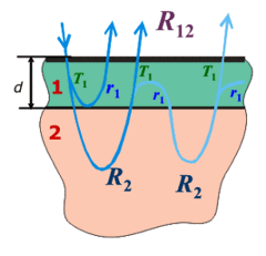
Fig. 6. Reflection from multilayer target Assume a target consists of layer of Material 1 with
thickness d deposited on top of bulk Material 2 (Fig. 6). Suppose the
following parameters are known: R2 – reflection function
from the bulk Material 2; r1, T1
– reflection and transmission function of Material 1. Then reflection function
R1,2 - from layered target is given by expression: where
Subtracting (13) from
(12) and neglecting multiple strong
scattering one arrives to the expression: Expression (14) conserves agreement with a principle of
invariance for the whole range of thicknesses d of
nonuniform layer.
Reflection function of multilayer targets The calculation of electron energy spectra
reflected from heterogeneous in depths targets is based on formulas
(7), (9),
(10), (14):
two-layer
targets, multilayer
targets. Single-deflection model &
Consistent solution of elastic problem
&
Consistent solution of elastic problem &
Fig. 7.
Different
multilayer
electrons
scattering models q0
– incident angle,
q - reflection angle, x1 – top
layer thickness, x2 – middle layer thickness, E0
– energy of incident electrons, R – reflection index, e1
- mean energy losses for the top layer material,
e2 - mean
energy losses for the middle layer material. Our experiments on the electron probing of targets prove that
the reflected electron spectra are highly informative. The developed spectra
interpreting technique might become a base for nondestructive layer-by-layer
analysis. Usual commercially available equipment for surface analysis, like
Auger spectrometers, suits well for the proposed electron spectroscopy
technique.
1. Remizovich V., Rogozkin D., Rayzanov M. Charged particles
path length fluctuations. (Energoatomizdat, Moscow, 1988) (in Russian).
2. Akkerman A.F. Simulation of trajectories of
charged particles in medium (Energoatomizdat, Moscow, 1991) (in Russian)
3. Fink M., Ingram J. // Atomic data. 4, 39 (1972).
4. Pines D., Nozieres Ph. The Theory Of Quantum Liquids.
(New York, Amster-dam: W.A. Bendjamin, Inc., 1966).
5. Mott N.F., Maessey H.S.W. The Theory of atomic
collisions (At The Clarendon Press, Oxford, 1965)
6. Riley M.E., MacCallum C.J., Biggs F. // Atom. Data and Nucl.
Data Tabl. 15, 443 (1975).
7. Liljequist D. // J. Phys. D: Appl. Phys. 11, 839
(1978).
8. Afanas'ev V., Lubenchenko A., Gubkin M. // Eur. Phys. J.
B 37, 117 (2004).
9. Akkerman A.F., Khlupin S.I., Average path length of
electrons with energies 0.1-100 kev up to inelastic scattering in solid /
Preprint IFVE
84-21. Alma-Ata. 1985. 43 с.
10. Tougaard S., Sigmund P. // Phys.
Rev. B 23, 4452 (1982.)
11. Afanas’ev V., Lubenchenko A. , Fedorovich S.,
Pavolotski A. // Technical Physics, 47, 1444 (2002).
12. Afanas`ev V.P., Naujoks D. // Phys. Stat. Sol. 164,
133 (1991).
13. Landau L.D. // J. Phys. USSR. 8, 201 (1944) .
14. Afanas`ev V.P., Yagova N.V. // Z.
Phys. B Cond. Mat. 92, 199 (1993).
15. Kulenkampff H., Rüttiger K. // Z.
Phys. Bd.137, 416 (1954).
16. Afanas`ev V.P., Naujoks D. // Z.Naturf. 46a,
851, (1991).
17. Afanas’ev V. P., Naujoks D. // Z. Phys. B
84, 397
(1991).
![]() Single
scattering event
Single
scattering event
![]() Elastic
cross section
Elastic
cross section
![]() Inelastic
cross section
Inelastic
cross section
![]() Multiple
scattering
Multiple
scattering
![]() Elastic
problem
Elastic
problem
![]() Inelastic problem
Inelastic problem
![]() Reflection function
Reflection function
![]() Multilayer targets
Multilayer targets
![]() Reflection
function
Reflection
function
![]() Conclusion
Conclusion
![]() References
References
For gases it is no problem to define what the ”elementary act” is. It is
scattering on a molecule or atom of a gas. Although by itself gases are complex
systems, but complete enough and valid data exist for most of its
characteristics. And one can compare this data with theoretical calculations [1,2,3]. In contrast, for solids usually it is not easy, and more often just
impossible to extract a separate process in the system of interacting particles.
In such cases one uses model representation, and the model’s adequacy is judged
by comparing of certain model based calculation and experiment.
Most often used is a model of electrons interaction with solids is based on
two-system representation [1,2,3]. One is a system of ions, internal electrons of
which are practically the same like for separate atoms; and a gas of quasi-free
electrons which consists basically of valence electron. This approach is
applicable to normal metals and, in some extent, to semiconductors. Transition
metals require more complex representation, like in frame of CLS-model (CLS
stands for ”Collective electrons – Localized electrons – Sheath electrons) [4].
In electron gas of normal electrons single-particle and collective excitations
of electrons can be efficiently separated and described in terms of dielectrics
theory. Relating to the processes of ionization and excitation of atoms, one can
use methods developed for single atoms. (Most of those are based on Born’s
approaches).
In accordance with E.Fermi we represent the process
of electron scattering in solids as one developed in two independent
channels: in elastic and inelastic. In elastic channel electrons
direction is changed in accordance with elastic cross section, without
any energy losses. But in inelastic channel electrons direction is
conserved and only energy losses take place. In other words the total
cross section may be presented as: 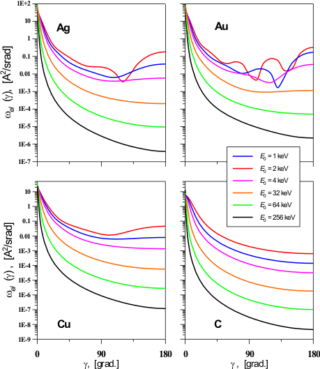
Electrons during their passage through a solid matter are losing their energy
not only due to ionization, but they experience strong inelastic scattering
related to production of phonons, surface plasmons, etc. Relative weights of
these interaction channels depend on energy of incident electrons, but anyway
contribution of inelastic channels remains sufficient up to the incident beam
energy of about 100 keV. Calculations usually face overwhelming mathematical
complications when all inelastic channels are taken into account. Therefore,
number of less detailed models for inelastic scattering are used [2].
Simple model, first proposed by Liljeqvist [7], is a modification of inelastic
differential cross section used for description of scattering process in gaseous
media:
Further refining of the model is based on representing of scattering on two
subsystems: one of ions and another of gas of quasi-free electrons. In the
normal metal electron gas, it is easy to separate single-particle
(electron-hole) and collective (plasmonic) excitations. Calculations of the
cross sections can be done in conformity with a formalism of a complex
dielectric constant. For practical calculation, electron energy losses can be
classified into losses for excitation of plasma oscillation (p) and
losses
for ionization of internal sheaths of atom (ion) [8]:
Fig. 3 compares inelastic differential cross sections calculated with different
models: solid line – formula (4), dash line – formula
(3).
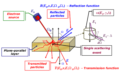
For the differential density of electron flow N0, impacted to
a target under the angle W0={q0,j0}
with the initial energy E0
and passing down to target at the depth of x under the angle W={q,j}
with energy E0-D (Fig.1),
transport problem can be represented as: (
(
Usually
density of electrons transmitted through a target is represented as: (
(
For practical purposes one needs to know either complete reflection and
transmission coefficients or spectra of reflected and transmitted electrons. Reflection
function defines spectra of electrons reflected from a layer of target material.
Analogously, transmission function defines spectra of electrons passed through a
layer of target material. Complete reflection (transmission) coefficients can be
calculated as an integral of the reflection (transmission) function over the
full range of energy losses and reflection (transmission) angles.
Electrons flow density passing through uniform media on certain depth can be
represented as a convolution of inelastic transmission function and path
distribution function. Both of functions are solutions of problems independent
one from another. Dividing of multiple scattering of electrons into scattering
in elastic and inelastic channels is a consequence of dividing of elementary
scattering act into two independent channels (1) [
Functions
AR,T и
Tin are solutions of two
independent problems: 1)
calculating of flow density of electrons gone through the path u in the
layer of thickness d0 (“elastic” problem); and 2) calculating
of flow density of electrons lost energy during going over the path u,
assuming that they move straight forward (“inelastic” problem).
 (
(![]()
![]()
Tin(u,D)
calculation methods have been defined by layer thickness d. If the layer
thickness is of inelastic mean free path order then direct computation of series
along the inelastic scattering repetition factor is fulfilled:
11)
Fig. 4 shows the spectra of electrons reflected from the
layer: right angle of incidence, angle of observation 63°
to the normal, initial energy 30 keV. Data points are taken from [15].
The target thickness is 0.44 mg cm–2 (triangles), 0.31 mg cm–2
(squares), and 0.16 mg cm–2 (circles). Continuous lines depict the
related spectra calculated by (7),
(9), (10).
Theoretical calculations performed with formula
(7), (9),
(10) are seen to be in good agreement with Kulenkampff and Ruttiger’s
experimental data [15]. The total inelastic cross section was determined from
data in [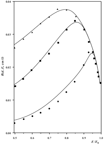
Continuous slowing down approximation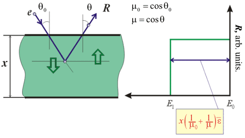
Continuous slowing down approximation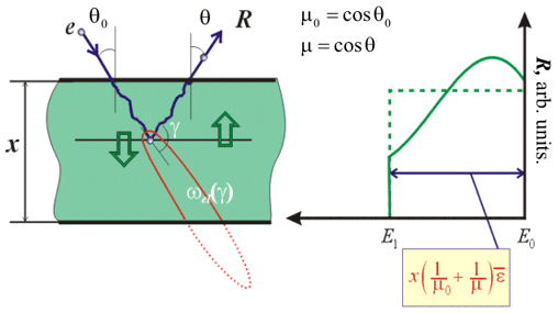
Consistent solution of inelastic problem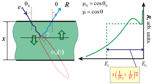
![]() -
integrating over energy losses and scattering angles range. Represent uniform
target of Material 1 like one consisting of two layers. Applying the same
approach like for
nonuniform target one can get the expression:
-
integrating over energy losses and scattering angles range. Represent uniform
target of Material 1 like one consisting of two layers. Applying the same
approach like for
nonuniform target one can get the expression:
Continuous slowing down approximation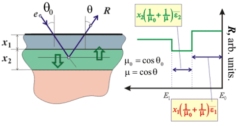
Continuous slowing down approximation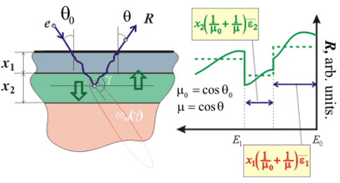
Consistent solution of inelastic problem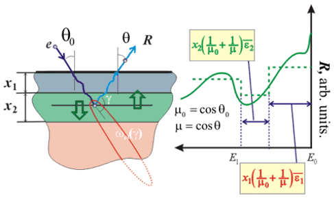
The self-consistent consideration of energy loss fluctuations makes it possible
to treat properly experimental data both in the range of low losses and in the
higher losses range responsible. This allows to describe the whole spectra
altogether: not the peak part only, but the dome-shaped part as well.
In this work, we demonstrate the method’s potential by analyzing of depth and
thickness of thin aluminum marker layer inside thick niobium target. The study
of such a structure by conventional RBS method, which is most widely used for
layer analysis, is impossible: only the niobium spectrum will be observed.
Generally, in contrast to RBS; developed electron spectroscopy can analyze both
light inclusions inside a heavy matrix, as well as heavy inclusions inside a
light matrix - equally efficient [17].
Error in determining the layer thickness and depth for the targets used in this
work does not exceed 1 nm. The errors of analysis originate from a number of
factors:
1. The basic (yet avoidable) error is associated with the large spread in data
for inelastic scattering cross sections win(D).
2. As soon as the present method compares spectra taken from a pure target and
from the target under analysis, the higher the difference Z
= |Z1 – Z2| of target components’ atomic
numbers Z1 and Z2, the lower the error.
3. Energy and current resolution of energy analyzer and Q-meter obviously
contribute to analysis error.
The relationship between the accuracy of depth profile analysis and the atomic
number Z depends on the layer depth, initial energy, and energy
resolution of the energy analyzer. So far, the detailed study of this subject is
beyond the scope of this work.
An ease of varying of the electron probe energy sets important advantage of
electron spectroscopy. The analyzed target thickness is comparable to the
electron transport length ltr. Since ltr ~
E02, the change in the beam energy from E0
= 10 keV to E0 = 30 keV increases the analyzed thickness
tenfold.
If the thickness of a multilayer structure does not exceed lin,
one can study it with a sub-monolayer accuracy using REELS technique. The
corresponding technique will be described elsewhere.


