COMMENTS
to
FIRST HET IF SYSTEM
Victor Belitsky
Chalmers University of Technology
S-412 96 Gothenburg, Sweden
Considerations About IF Frequency Choice
The main goal for HET instrument is to have state of art sensitivity
of all mixers. It is obvious that the resulting system noise temperature
depends on IF chain noise temperature, the mixer noise temperature
and the RF conversion loss. With submm wave SIS mixer conversion
loss optimistically  6 dB we will
have IF system noise contribution to the system noise 4 times
of IF noise temperature. Correspondingly we must optimize the
IF noise temperature keeping in mind SIS or HEB mixer specific
features, HEMT transistors potential to have the best noise temperature,
cryogenic constraints.
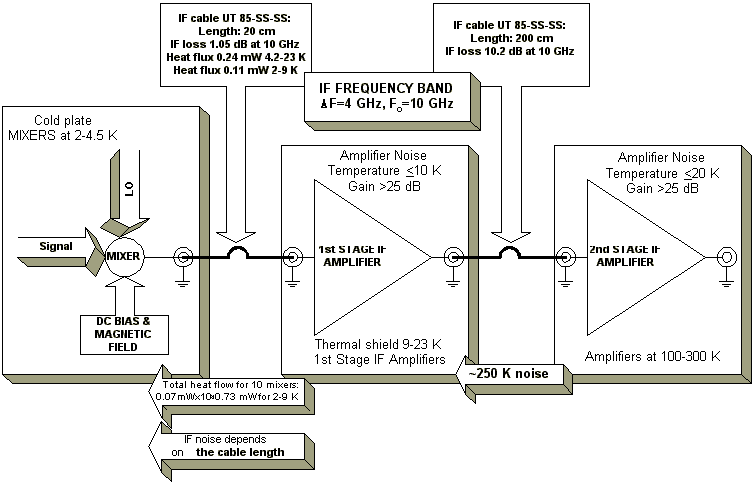
In the provisional IF system design (please see Figure 1 for block-diagram)
we have the IF frequency 10 2 GHz with
total 4 GHz bandwidth.
The high center IF frequency (for SIS mixers typical IF center
frequency is 1.5 … 4.5 GHz with 1.. 1.2 GHz band) have the
follow advantages:
- With high RF frequency it is easier to provide SSB operating
(USB is separated from LSB by 2xIF center frequency). NB. HET
band is from about 500 GHz up to 1.2 THz continuos coverage plus
possible THz channel at about 1.8 THz.
- With high IF center frequency the LO band can be reduced down
to 2xIF center frequency times of LO source number.
- By keeping IF center frequency high even for 4 GHz wide IF
band we have DIF/IFcenter=0.4
that simplifies the IF amplifier design (relatively narrow-band
IF amplifier).
- Still there is a hope that InP transistors will solve the
problem of power dissipation so that such amplifier can be "integrated"
with SIS mixer. InP HEMT transistors are demonstrated to be better
for frequencies above 10 GHz.
Point 1 is listed here just for keeping general approach,
while after long discussions within HIFI group during 1996 DSB
operation was chosen for HET instrument. Point 2
is related with available LO power at higher frequencies. It is,
perhaps, the most serious recent constrain implying use of diplexers
for LO signal injection for high frequency end of the HET band.
Furthermore, by using several switchable LO sources per one mixer
band one can gain up to 2xIF center frequency per each source
in LO frequency coverage.
However, besides the advantages there are also
drawbacks of using the high IF center frequency.
- The state-of-art noise temperature of microwave amplifiers
at cryogenic temperatures can be estimated as
 1 K/GHz
according to [2] (I have a few references with noise temperatures
confirming that at least below 12 GHz). That gives for 4
 2 GHz
IF frequency TIF4
  4 K
while for 10-12 GHz TIF10
  10 K
(see for instance CTH design for limb sounder IF amplifier) which
is more than 3 dB difference.
- Looking at provisional IF chain block diagram one can find
the coaxial cable connecting the mixer and 1st IF amplifier
is a critical component. Indeed, it is much better to get rid
of any long cables (with losses!!) in between a mixer and IF amp.
However, due to cryogenic constrain we need to isolate thermally
the SIS mixers from external heat flow. Total power dissipation
at SIS mixer cold plate is about 5 mW only according PDD. Hence,
we need to use pure stainless steel cable (or other low thermal
conductivity material) and, perhaps, increase the length of the
cable to keep thermal flow through it at the certain desirable
level. The calculation I made for thermal flow shows that with
30 cm cable the thermal flow is as great as 0.7 mW (in the Table
1 it was used data from reference 1 see also Figure 1) for 10
IF amplifiers we have in the HET assuming that IF amps are at
9 K ambient temperature. Low heat conductivity of the cable material
implies higher RF resistive loss (even in spite of the
silver covered inner surface of the shield and rod of the cable,
like UT 85 SS-SS). The cable will increase the resulting
noise temperature of the IF amplifier. Again, the loss in the
cable is frequency dependent, so typically the loss per meter
of the cable for 10 GHz is 2.2 dB higher than for 4 GHz. You can
see the resulting noise temperatures due to the cable loss in
the Table 1.
Table 1
Table of comparison of the HET IF system components at 10 2 GHz and 4 2 GHz and 4 2 GHz 2 GHz
|
| Component | Main characteristic
| Value at 10 GHz | Value at 4 GHz
|
| Cold IF amplifier | Noise Temperature
| 10 K | 4 K
|
Cryogenic IF cable
UT 85 SS-SS
| Loss per 1m | 5.1 dB/m
| 2.9 dB/m |
Cryogenic IF cable
UT 85 SS-SS
| Heat flow mW over 1 cm
with temperature differ.
| 4.6 mWcm 4.2-23 K
2.2 mWcm 2.5-9 K
| 4.6 mWcm 4.2-23 K
2.2 mWcm 2.5-9 K
|
| IF noise temperature calculated based on above
| 14.2 K | 4.9 K
|
HET IF SYSTEM (Provisional, suggested in PDD, thin Red Book)
- Another issue that limits IF band of an SIS mixer is capacitance
of SIS mixer. Figure 2-4 display the SIS junction topology and
equivalent circuitry for the SIS mixer at RF and IF. The main
conclusion from that is that the capacitance that is a sum of
the SIS junction capacitance and the capacitance of RF integrated
tuning circuitry. The latter is result of drastic difference of
RF and IF, so that the RF tuning microstrip circuitry must be
considered as lump capacitor at IF. Without special precautions
the capacitance together with 50
 impedance
of the coaxial cable connecting IF amplifier creates classical
filter structure with corresponding IF coupling loss (Figure 5).
Typical solution used to solve this problem like to reduce the
cable impedance (by employing transformers) is not useful with
SIS mixers. This will lead to immediate increasing of the mixer
conversion loss L, which is in proportion to the ratio of ~RRF/RIF,
where RRF is the mixer RF impedance (constant for given
mixer and RF frequency) and RIF is the load at IF mixer
port. The lower RIF the higher the ratio and the more
mixer loss.
The same comment can be applied for the series inductance compensation
presented at Figures 6-9. Q-factor of the compensation circuitry
has to be to kept at reasonable level (low to avoid critical dependence
on the circuitry parameters but enough to get resonance). That
with decreasing of the compensation inductance L at high frequency
for given circuitry parameters lead to reducing the impedance
connected to the inductance from IF amplifier (again by using
transformer). Figure 9 shows results of modeling for such a compensation.
Note that this circuitry becomes very sensitive to the varying
of Cj, Ccomp and L that complicate the mixer
design. We still lose of about 5 dB all together due to
coupling circuitry and decrease of RIF (see
paragraph above).
SIS junction: topology
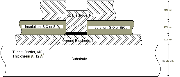
Figure 2. An SIS junction is planar mm-scale size structure
that is alike planar capacitor. The figure shows typical dimensions
of cross-section of Nb-AlOx-Nb SIS junction. Thickness
of the top Nb electrode and SiO/SiO2 dielectric layer
can vary depending on an integrated tuning circuitry.
SIS junction: RF equivalent circuit
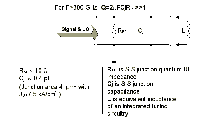
Figure 3. RF equivalent circuit for SIS junction
mixer. Integrated tuning circuitry which is the only solution
to provide RF coupling in some frequency band is schematically
shown by inductance L. In practice the tuning circuitry
is a set of planar transmission lines providing resonating out
the SIS junction capacitance, Cj, and transforming of the
SIS junction RF impedance to match the latter to Signal &
LO guide system (waveguide mount or planar antenna).
SIS junction: IF equivalent circuit
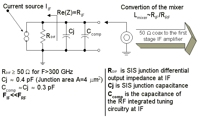
Figure 4. IF equivalent circuit for SIS junction
mixer. Integrated tuning circuitry that is the only solution to
provide RF coupling in some RF frequency band is schematically
shown now by capacitance Ccomp due to FRF>>FFI.
Possible improvement of SIS mixer-IF coupling
Reducing the RIF or the circuitry IF capacitance
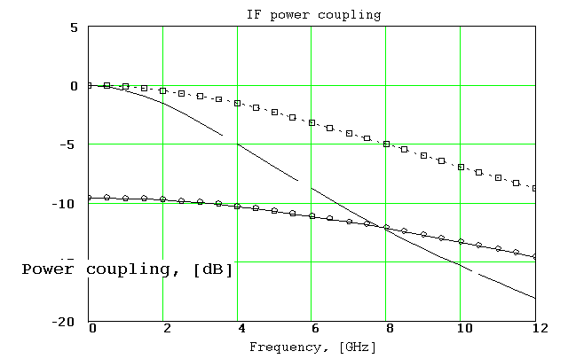
Figure5. Solid line presents SIS junction IF coupling to
50  cable for Cj+Ccomp=0.7 pF; o-line
shows IF coupling with impedance of 16.7
  in stead of 50
  . While square-line shows
possible improvement in the case of reducing SIS mixer capacitance
down to 0.35 pF.
Series inductive IF compensation
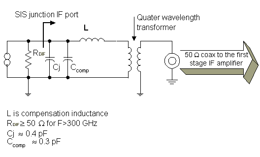
Figure 6. Principle of IF series inductance compensation.
For the given above parameters it was modeled the circuit above
for different values of the inductance L. The choice of the inductance
was predefined by capacitance CIF=Cj+Ccomp
and desirable frequency of IF (4 and 10 GHz center). The quarter-wave
transformer was used to reduce the impedance of 50  to keep Q-factor at reasonably low level (to avoid critical dependence
on the circuitry parameters) and to allow the circuit to work
towards higher frequency while L is reducing.
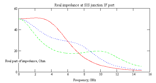
Figure 7. Principle of IF series inductance compensation:
the real part if impedance substituted to the SIS IF port.
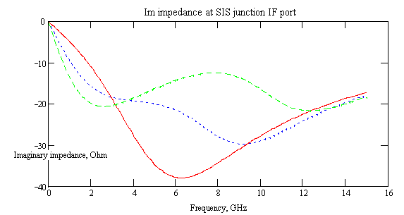
Figure 8. Principle of IF series inductance compensation:
the imaginary part if impedance substituted to the SIS IF port.
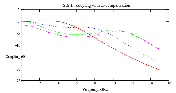
Figure 9. Principle of IF series inductance compensation:
the SIS mixer -- IF coupling (including loss due to drop of the
real part of impedance (see Figure 7)). The magenta dash-dot trace
shows changes in the IF coupling for 20% change of SIS mixer capacitance,
confirming that such a compensation is very sensitive to the parameter
values and might be tricky to use.
- Hot Electron Bolometer mixer (HEB), the new element for heterodyne
mixer technology differs from SIS mixer by inherently limited
the upper IF frequency. In the case of using really low-noise
IF amplifier the IF upper frequency of HEB mixer can be, perhaps,
extended up to 56 GHz with drop of IF signal towards
the high frequency of the IF band , however, with the same system
noise temperature. It is clear that using of HEB mixer in the
HET will require another IF amplifier than provisional for SIS
with 10
 2 GHz IF band.
SUMMARY
Table 2
Table of comparison of the HET IF system components at 10 2 GHz and 4 2 GHz and 4 2 GHz 2 GHz
|
| Component | Main characteristic
| Value at 10 GHz | Value at 4 GHz
|
| SIS junction mixer |
IF coupling†
without compensation/with L-series compensation
|
-15.5 dB/-5 dB |
-5 dB/-1.5dB |
| HEB mixer | IF coupling
| maximum IF cutoff frequency 5..6 GHz
|
| IF noise temperature calculated on based above IF chain (the cable output)
| 14.2 K | 4.9 K
|
| IF contribution into the system noise assuming 6 dB SIS mixer RF conversion loss only
| 56.8 K | 19.6 K
|
| IF contribution into the system noise assuming 6 dB SIS mixer RF conversion loss as well as IF coupling (with series L-compensation)
| 179 K | 27.5 K
|
The SIS mixer IF chain with 10 2 GHz band
is incompatible with HEB mixer technology. We have to consider
that issue from technical point of view (we can have two different
IF chains) as well from point of view of the project cost.
Possible reducing of the IF center frequency increases importance
of HET LO system assessment. Perhaps using of 3 and even 4 LO
source for each mixer band (3 LO for the 3rd and 4
LO for 4th mixer) can solve the problem. Increase in
the quantity of LO sources will be compensated (at least partly)
by lower cost of each source. We also can benefit from using passive
(beamsplitter) LO injection scheme that will simplify the HET
optical architecture. The lower frequency LO sources are going
to be more reliable. Then, perhaps, we can reduce redundancy level
for low band mixer(s) to compensate complexity of having extra
LOs for high frequency end mixers.
Possible solutions
1 SIS mixer development program focused on IF coupling
in 8-12 GHz IF band
- integrated IF tuning (only for open structure mixers, no space
in waveguide mount!).
- decreasing the circuit capacitance (decreasing the SIS junction
size requires E-beam lithography, submicron area junctions are
less stable and much more sensitive to static discharge).
2 Changing the IF frequency to 2-6 GHz band with using
balanced IF amplifier [2]. This also requires development work.
However, this solutions brings use for both HEB and SIS mixers.
References
- "The Heterodyne Instrument Concept for FIRST" by
Eri Cohen, Neal Erikson, Margaret Frerking (editor), Paul Goldsmith,
Andrew Harris, Charles Lawrence, MJ Mahoney, Tom Phillips, Jonas
Zmuidzinas
- Ilcho Angelov, Microwave Technology Dept., Chalmers University.
Privet communication.
- Micro-Coax Components, Inc. Catalogue.
See also NRAO MMA receiver page about IF choice:
http://www.tuc.nrao.edu/mma/mma.html
NB:
The first time these notes were presented during Opto-Mechanical
Workshop (devoted to the HET optical architecture) at SRON, Groningen
March 13, 14 1997. I found some points in my at SRON presented
paper that needed more clear comments and some correction.
Some pictures and numbering have been transferred into HTML format
not correctly by
MSWord Internet Assistant.
You can get this file in form of MSWord 6 document, contact me.
Victor Belitsky
Radio and Space Science Department
Chalmers University of Technology
S-412 96 Gothenburg SWEDEN
E-mail belitsky@ep.chalmers.se,
tel. +46 31 7721893
FAX +46 31 164513
 6 dB we will
have IF system noise contribution to the system noise 4 times
of IF noise temperature. Correspondingly we must optimize the
IF noise temperature keeping in mind SIS or HEB mixer specific
features, HEMT transistors potential to have the best noise temperature,
cryogenic constraints.
 2 GHz with
total 4 GHz bandwidth.
 1 K/GHz
according to [2] (I have a few references with noise temperatures
confirming that at least below 12 GHz). That gives for 4
 2 GHz
IF frequency TIF4
  4 K
while for 10-12 GHz TIF10
  10 K
(see for instance CTH design for limb sounder IF amplifier) which
is more than 3 dB difference.
 2 GHz and 4
 2 GHz
2 GHz
 impedance
of the coaxial cable connecting IF amplifier creates classical
filter structure with corresponding IF coupling loss (Figure 5).


 cable for Cj+Ccomp=0.7 pF; o-line
shows IF coupling with impedance of 16.7
  in stead of 50
  . While square-line shows
possible improvement in the case of reducing SIS mixer capacitance
down to 0.35 pF.

 to keep Q-factor at reasonably low level (to avoid critical dependence
on the circuitry parameters) and to allow the circuit to work
towards higher frequency while L is reducing.


 2 GHz IF band.
 2 GHz and 4
 2 GHz
2 GHz 2 GHz band
is incompatible with HEB mixer technology. We have to consider
that issue from technical point of view (we can have two different
IF chains) as well from point of view of the project cost.